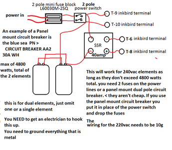
I am turning a cabinet into an electric smoker. I am going to use 220V 20 AMP CIRCUIT. I will use a 3400-watt oven element.
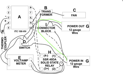
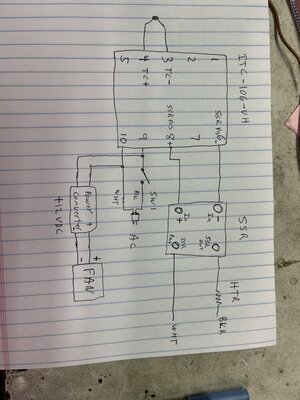
Here is my parts list and a not electrician schematic I did. I would love any productive input or thoughts on this
PID Parts List
Here is my parts list and a not electrician schematic I did. I would love any productive input or thoughts on this
PID Parts List
- Inkbird PID Thermostat °F °C Display Stable Digital Temperature Controller Heating Cooling Control ITC106VH 40DA SSR Output Solid State Relay Alarm K Sensor
- COOLWEST Transformer Driver Power Supply 24W 12V for LED Strip Lights and G4, MR11, MR16 Light Bulbs
- Anmbest 2PCS 5010 Silent Brushless Cooling Fan 2 pin Brushless 5CM Fans DC 12V 0.1A 50mm X 50mm X 10mm for Cool 3D Printers Parts PC Case CPU Cooler Sleeve Bearing 7 Blades & 50mm Black Fan Finger Grill (2 Pk)
- Baomain Red Light DPST ON/Off Snap in Boat Rocker Switch 4 Pin 16A/250V UL TUV List (1, Red)
- DROK Volt Amp Meter, AC 500V 200A Digital Voltmeter Ammeter Panel, 0.39 Inches LED 2in1 Multimeter, 2-Wire Voltage Amperage Tester Gauge with Current Transformer
- Twidec/2M NPT 1/2"inch (6X100MM) Pipe Thread Temperature Sensor Probe Two Wire Temperature Controller (0~600℃) 304 Stainless Steel K Type Thermocouple MT-205-1/2 & 1 Set GX16 Aviation Plug Socket 2 Pin Screw Type Male Female Metal Aviation Wire Connecto
- uxcell PG13.5 Cable Gland Waterproof IP68 Nylon Joint Adjustable Locknut with Strain Relief for 7-11.5mm Dia Wire, 2 Pcs
- 40DA SSR Output Solid State Relay
- 2 Pack Terminal Block 4 Circuits 20-30A Dual Row Screw Terminals Strip Includes 20 Heat Shrink Wire Connectors Electrical Wiring Kit
- Beaquicy WB44T10011 Oven Bake Element - Replacement for Ken-more G-E Oven, Replaces: WB44T10059, 820921, AH249286, EA249286, PS249286, B003BIGDEA Voltage 220 Volts Wattage 3410 watts