Getting ready to build first PID...

  • Some of the links on this forum allow SMF, at no cost to you, to earn a small commission when you click through and make a purchase. Let me know if you have any questions about this.
SMF is reader-supported. When you buy through links on our site, we may earn an affiliate commission.

ericksaint

Fire Starter
Original poster
Jun 12, 2017
67
11
So I've got another thread going on the "other builds" forum about running a hotplate in my gasser for doing low temp stuff like sausage etc.

I've got a pretty firm grasp on what I need to do to get the pid wired, just need to get the parts ordered.

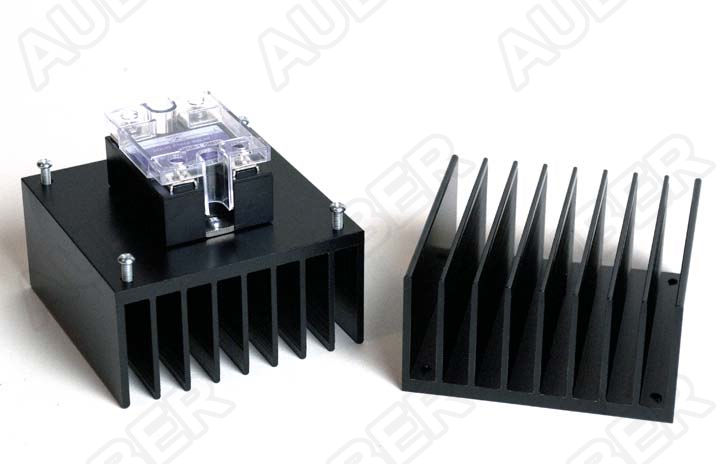
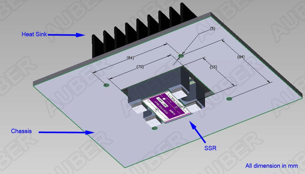
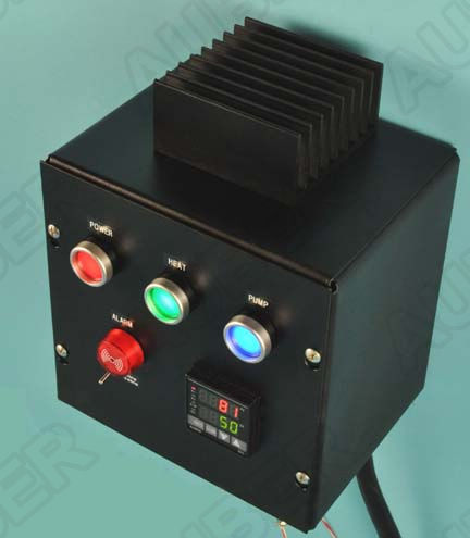
My question is about mounting the SSR and heatsink. I'm using a pvc box. Are people just mounting to the inside of the box? Or does that get too hot. I saw one pic online where a guy cut a slit in the side of the box and jammed the first set of fins in the slot.

Not sure what to do. Search seemed to pull up a bunch of threads that don't have pics attached anymore.

Here's the box, just the same type of box it seems everybody else is using. 20171128_204907.jpg
 
Well the original question got zero response, am I asking on the wrong place?

Anyway, on to a new question. Is it normal for the SSR in a pid system to have a higher than zero voltage when not calling for power, but not high enough to operate?

I ask because with a tester plugged into the outlet I still see faint lights when the outlet is supposed to be "off" according to the pid. Then when it calls for power they get full bright. If I use a lamp plugged in it seems to be working as it should, the just isn't enough power to turn on the lamp.

This should be "off" and I'm still getting 94 volts from the SSR, when is calling for power I get about 118v.
20171202_085415.jpg
 
To test your SSR apply 9V DC to the trigger side. If your light bulb lights and it doesn't light when you remove the 9V then the SSR is good. Actually you can use any voltage from 3-32V.

As to your first post, how many amps does your hot plate pull at full power?
 
Last edited:
SSR's do not test like a dry contact relay would. There is a small amount of leakage (this is normal) that creates a feedback loop so the SSR can actually work. You need a load connected on the load side (say a 40 watt light or similar) for them to function and read properly. If you try to read output switching with no load other than the meter, it will not read right.

The PID output to the SSR can be tested as it is plain old low voltage DC.

Cut and pasted from the Auber Instruments SSR FAQ page:

4. Can I test a SSR with a multimeter?

4.1) Q: When there is no input for the SSR, I can still measure a live voltage on output of the SSR. Does that mean the SSR is defective?

A: No. The SSR is a semiconductor device that has a leak current. The leakage is less than the range of 0-30 mA. Large capacity SSR has higher leakage than the small capacity SSR. If you measure the output voltage at an open circuit condition, you will get a live voltage that is the same as the AC input. (This is the typical case when user tests the output with a voltage tester).That does not necessarily mean the SSR is burned through. However, if there is a load (more than 10 Watt, such as a heater) on the output, you should not detect any significant voltage because it is drained by the load.

4.2) Q: When I measured the resistance of the output of SSR, it changed from mega ohm to 1-20 kilo ohm range when an input trigger is applied. Should it be zero ohm?

A: No, it should not. This is because almost all AC SSR on the market has a zero voltage crossing detection circuit. It will not turn on (change resistant to zero) unless it detects an AC voltage that is changing the flow direction (across zero voltage). The zero voltage detection function is for protecting inductive loads. Without an AC load, the output resistance will never change to zero. It should be noted that changing the resistance from mega ohm to kilo ohm does not mean this SSR is good. But It tells you it has not been burned open and is responding to input.

4.3) Q. How to test an AC SSR correctly?

A. The most reliable way is connect the output with a 40W light bulb. If the light bulb responds to the input trigger, the SSR is fine. You can also refer to this guide (www.crydom.com).

As to the heat sink, they make heat sinks that are made to surface mount to a flat surface with the SSR on top and another type which fits over a cutout in the box slightly larger than the SSR body. In the 2nd type the SSR mounts to what will be the bottom of the heat sink and remains inside the box with the fins mounted outside the box. Make sure to use thermal conductive grease when attaching the SSR to the heat sink, and with heat sinks, bigger is better (ie, a 40amp rated heat sink will work with a smaller amperage SSR). I would consider up sizing the heat sink with a plastic box.

This is the type of heat sink I'm talking about..... This is an Auber 40 amp heat sink (which will work great with a 25 amp SSR)

HS40Ea.jpg

AssemblyHS40ET.jpg

Top_viewa.jpg
 
Thanks for the responses.

To test your SSR apply 9V DC to the trigger side. If your light bulb lights and it doesn't light when you remove the 9V then the SSR is good. Actually you can use any voltage from 3-32V.

As to your first post, how many amps does your hot plate pull at full power?

I'm a bit rusty on my ohm math but it's a 120v 1000w element, I think that works out to about an 8.3 amp draw.

SSR's do not test like a dry contact relay would. There is a small amount of leakage (this is normal) that creates a feedback loop so the SSR can actually work. You need a load connected on the load side (say a 40 watt light or similar) for them to function and read properly. If you try to read output switching with no load other than the meter, it will not read right.

The PID output to the SSR can be tested as it is plain old low voltage DC.

That copy perfectly explained what I was seeing. I was seeing line voltage with nothing plugged into the outlet, and the 94 volts with just the plug in tester as a load, but when I was using a CFL bulb to test and it was showing only a 7 volt load when the pid was "off". This is kind of new to me. But this puts me at ease that everything it working as it should.

Here is a link to the pid kit I got from amazon. It came with a 40A SSR and heatsink. I pulled the hotplate in from the garage when I came home, I'm going to bench test with the hotplate so I'm using the actual load and see how hot that SSR heatsink gets running the plate.
inkbird.jpg

I've seen this pic floating around the web, but it's about the only one I saw with the heatsink outside the box like that.
heatsink.jpg
 
This is the temp of the top of the heatsink after about 30 minutes of the element being full on.
20171202_204743.jpg

And this is the temp at the very bottom fins of the heatsink where it has the holes to mount it to the box.
20171202_204753.jpg

No thermal compound installed for these pics, but I just found a syringe of the good stuff I used on the CPU the last time I built a PC. So I'm going to spread some of that when everything cools and remount the SSR to the heatsink.
 
So everything seems to be working as it should. The thermocouple is off so I need to get that calibrated. The end on that thermocouple is so short I don't want to try to calibrate with water and risk killing the thermocouple. So I made up a jig to put my maverick (spot on temp wise) side by side with it in the oven to figure out what my offset needs to be. I suppose I could just do it at room temperature as well to get the offset number, is there any issues with that?

Here's the jig, ugly but it works. Lol.

20171203_143602.jpg

When it first gets to temp, and shuts off the SSR, it always overshoots the temp by at least 5+ degrees, will this level itself out after I get it in the smoker and run the auto tune?

20171203_144234.jpg
 
SmokingMeatForums.com is reader supported and as an Amazon Associate, we may earn commissions from qualifying purchases.

Hot Threads

Clicky