Watlow PID Controller help needed

  • Some of the links on this forum allow SMF, at no cost to you, to earn a small commission when you click through and make a purchase. Let me know if you have any questions about this.
SMF is reader-supported. When you buy through links on our site, we may earn an affiliate commission.

JckDanls 07

Legendary Pitmaster
Original poster
OTBS Member
SMF Premier Member
Sep 10, 2011
8,018
2,652
Tampa area, Florida.
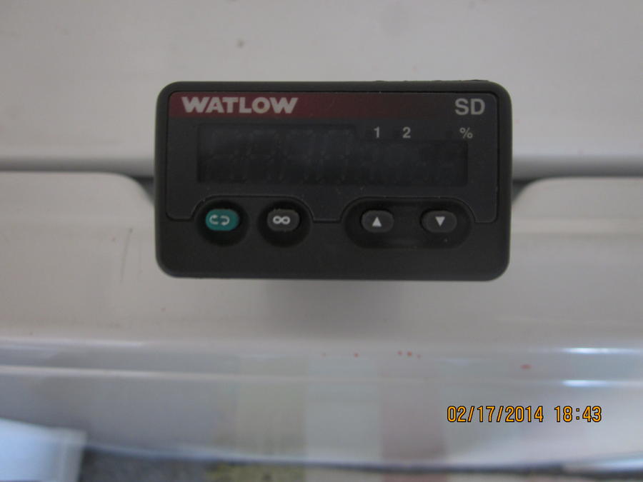
I was given this Watlow controller.. I have a MES 30 that the controller is shot on and want to use this one in it's place ....


I was looking for a wiring diagram and found this... http://www.watlow.com/downloads/en/manuals/sd rev f 5-31-06.pdf

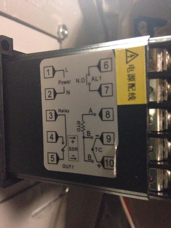
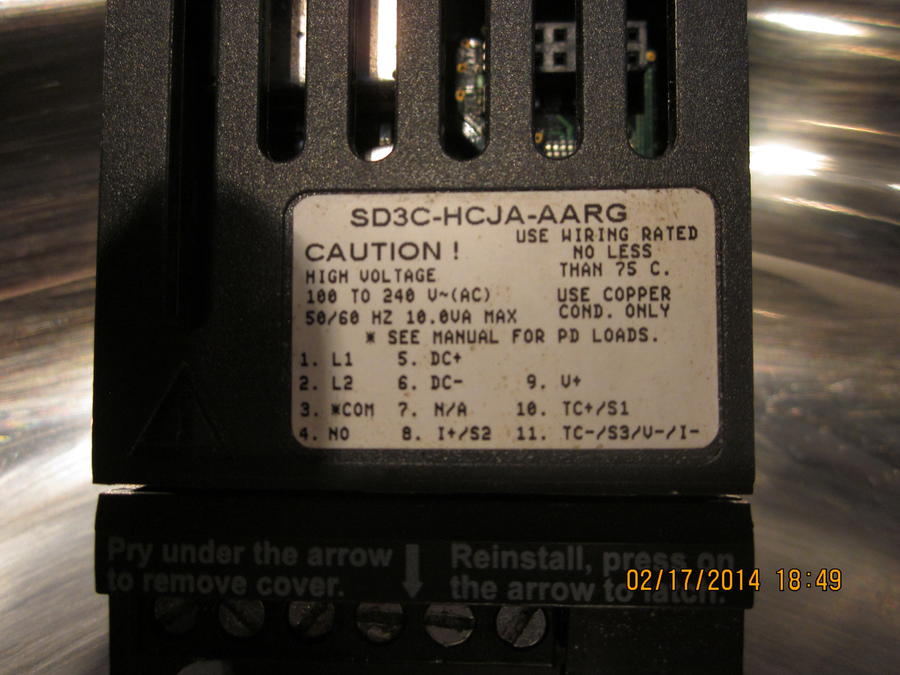
I'm a little confused on the wiring input (power supply)... The diagram for this controller (1/32 DIN) on page 11 of the PDF shows high voltage L1 goes to 1 and L2 goes to 2... is this for 110v or 220v ? I always thought L1 and L2 referred to 220v... If it's for 110v is the white common considered L2 ? Or does the white common go to #3 on controller.. here's a pic of the diagram on the controller (click on it to enlarge)...


#3 on the diagram says " * COM" ... is this for Common of a 110v ? In the picture above it says.. " * See manual for PD loads"

here's a pic of the back


As for the thermocouple ... I couldn't find any info on what type of thermocouple I need... If somebody could shed some light on which one I need it would be very much appreciated....
 
Handymanstan has it covered.

L1 and L2 are your AC voltage connections.  Wiring is on page 11, in figure 11a for 110v.  Just hook the black and white wires from your 110v to terminals 1 and 2.

DO NOT confuse "Com" on terminal 3 with common which can be sometimes used for the neutral leg of a 110v circuit.  On this PID the "COM" is for output 2 if used.  Use only L1 and L2 for 110v AC power.

Any time you have wiring info on a sticker attached to the device, go with that over the printed PDF (but in this case they match, which is what I would expect from a quality company like Watlow.  Not so much with Chinese products though).  Watlow is first quality commercial grade stuff.  That PID is a keeper for sure.

Here is your sticker


From your your model number on the sticker, SD3C-HCJA-AARG, this is what you have....

Model SD3 1/32 DIN with "other than a universal process output installed for output 1".  Breakdown is as follows:
  • H - High voltage AC power wiring (input power for the PID) on terminals 1 & 2 (100 to 240v AC range)
     
  • C - Output 1 switched DC for SSR control - supplies 30mA maximum (this is plenty for triggering a smoker SSR), supplies 6 to 12v DC output (again perfect for triggering the SSR's you will see in smoker builds here).  Terminal 5 is DC+ and terminal 6 is DC - output to the SSR (polarity does matter)
     
  • J - Output 1 mechanical relay - plain old mechanical relay for up to a 2amp load.  Will handle up to 240v AC or 30v DC.  This is a simple relay and does not supply any power, it is only a controlled "switch" type relay.  Terminal 3 is the common and terminal 4 is "normally open" and closes when triggered by the PID.
     
  • A - not in the manual (that I saw), perhaps "A" for Absent or not used?  That position appears to be for the Output 3 configuration and is appears to be absent in your unit as the PDF shows terminals 12 to 14 used depending on what internal configuration the unit has.  It is common not to have a third output (and the biggest clue is you don't have terminals 12 to 14 on your model sticker).
     
  • As to the temperature sensors you have many options that can be programmed by the user (you) depending on what you have.  Should work with and RTD sensor or J, H, T, E, N, C, D, PTH, R, S, and B type thermocouples (pretty much anything you might encounter will work - Watlow is good stuff and commercial grade).  Figures 12a and 12b on page 12 of the PDF cover the most common sensor hookups.

    NOTE ***YOU MUST configure the software in the PID to match the sensor type you use or you will get incorrect readings***
Short version for 99.9% of the smoker controllers out there would be.....

Terminal             Goes to

-----------------        -------------------------------------------------

1 & 2                 110v AC power (polarity does not matter)

3 & 4                 Not used

5 & 6                 DC triggering voltage out from PID to SSR trigger input (polarity does matter)

7                       Not used

8                       Only used if you have a RTD type sensor

9                       Not used

10 & 11              Used for thermocouples, and used for RTD sensor (along with terminal 8 for RTD only).

That should cover the hookup of the unit. 
 
That's perfect.. thanks you guys... when I get a thermocouple I may need some help configuring....
 
S O B .. had a short story all wrote up and hit the wrong button and cleared the editor ....

I got this TC (thermocouple) ... http://www.auberins.com/index.php?main_page=product_info&products_id=101

Hooked it up to the controller.. selected K style (default was J style) ... Did a boiling water test... was dead on.... Today I wired everything into an MES 30 ( as that's what I want to install it on).. turned power on and TC was reading (ambient) in the 300's (trusty maverick was reading 75`)... It took WELL over a half hour for it to come down to around 115`-120`.... So I played around, selected different styles.. still stayed around 115` when I put it back on K style... unwired everything except power and TC... brought it back in the house... boiled some water and it was only reading around 198`-200`.... so for now I set the calibration at +13 so it would read 212` ... thoughts and comments...

Also.. I tried to use the MES's TC... don't know what style it is.. tried all settings.. but didn't wait for numbers to come down like the aftermarket one.... Can the Mes's TC be used ? and does anybody know what style it is ?
 
Last edited:
ok... Got the thermocouple all straightened out and working correct.... So I have been trying different SET values and it seems it wants to run 5` cooler than what I set it at... using ET 732 for confirmation.. all 3 probes (2 mavs, 1 to controller) calibrated in boiling water and all 3 match at 212`.... example; set at 200`, smoker temp was 195`... raised set value to 225` , smoker ran at 220` ... raised set value to 250` , smoker ran at 245` ... looking for info on how to adjust which setting that would even these readings up (smoker to run at the actual set value) .... I know it's only 5` but i'm kinda finicky that way .... any help would sure be appreciated ...

Don't forget... here's the manual for this controller.... http://www.watlow.com/downloads/en/manuals/sd rev f 5-31-06.pdf

Thanks you guys .... more questions to come, I'm sure....
Evening Keith.  Different kinds of TC work different and can take a few minutes to sync up.  Try setting them all together and wait 5 minutes and then see the difference.

 Did you use the auto tune?  It should go like 5* hotter then set point then drop 2-5* below set point then up 2* above then 1* below then it should be set and auto tune will turn off.

The cal function changes the TC temp – or+ number or in this case 5       looks like it is the 5th choice.  Press the advance button 5 or 6 times and change to 5

hope this helps

Stan
 
Hey Stan... I understand the Cal changes of the TC... but I did the boiling water cal. and was reading dead on at 212`.ough .. I thought that you only change the Cal. number if the TC was reading off in boiling water ? Since it was reading accurate at 212` I did not change. .. Since the TC was reading accurate, it said the smoker was running at only 220` when the SV on the controller was set at 225`... I don't want to change the TC to read what the SV is as this would not be the actual temp in the smoker.... MAN.. starting to confuse myself now.... LOL...

As far as auto tune goes... I did run it one time when it got close to target temp upon start up .... target temp (SV) was at 200` for start up... at 190` I started AT...

As I said in OP,this controller was giving to me.. i don't know what it was used for by it's previous owner.... so i went through some of the settings comparing them with default settings.. i did find one setting that was changed from default and that was Ctr 1 (page 28 of manual) ... Control Method 1 default is Vrtb (variable time base) ... The controller is set on Ftb (fixed time base) .. I don't know if that has anything to do with the 5` difference between the two readings.....
When I stick my thermopen in meat it reads in 3 seconds.  To get to ambient temp there guide says you set on counter for 3-5 Min's to get reading.  There is a difference in what you are measuring.

Air or meat or water its all different and the way the different kinds like J or K or whatever mav is.

Get the smoker to 150* and run the auto to 200* let it learn just the 50* spread.  I am not sure about the ctr1 I would set it to default and try it.

Stan
 
First, I would not use a Maverick as a benchmark and quibble about a 5* variance.  The error may well be in the Maverick units. Second, you are not talking about controlling critical temperatures to a 1/2 degree here.  5 degrees tolerance (assuming that is the actual difference) is perfectly acceptable for smoking meat.

As to VTB vs FTB......

Variable Time Base (VTB) is pretty specific to the Watlow PID's. With the unit set to FTB, it turns the output on and off every "x" seconds, but with the VTB it turns it on and off every "x" electrical cycles (you will also have to set what electrical service you have, ie....50 or 60 Hz).  I do not see the advantage of VTB in the heating setups we are talking about.  Switching the output every x/60ths of a second (1/20th sec) vs every x seconds will make little difference in the performance in a smoker.  For other more critical processes, there can be a use for VTB (remember these PID's were originally created for a wide range of process control situations).  You can fiddle with the fixed time base cycle duration in the Ftb 1 setting. Default value should be 5 seconds for a SSR output.

Also try running your autotune from a cold pit.  You may have to run more than one autotune cycle to get the performance you want, and it may take a bit.  Let the PID do it's job.  There is also a tolerance range setting (how tight it tracks the set point).  Check to see what yours is currently set for. You can change the calibration offset if needed.
 
Last edited:
Handymanstan and dward51 I could use both of your help. Getting my controller hooked up is the only thing holding me back. I would like to talk to one of you if not both online to help me figure it out. I only bought it cause everyone said that it was the way to go. Other than that I haven't got a clue. If you could draw me a picture I might be able to figure it out. This is what I have. I have a 2200 watt element that it's going to run.
 
Afternoon Kunze... First I must say... If your not comfortable doing electrical wiring you should hire an electrician .... You say your gonna use a 2200 W element... I'm pretty sure that will be a 220 V element... is this true ?? We need to know that before we continue ...Also.. will you be using a dedicated breaker (recommended) ?? ...
 
Last edited:
ok... I don't have a drawing but I will explain the best I can and then see if your comfortable doing it...

first ... MAKE SURE ALL POWER IS TURNED OFF BEFORE STARTING.... The power supply to the controller will/should be 4 wires (12 gauge)... 1 RED (line 1).. 1 BLACK (line 2)... 1 WHITE (common/neutral)... 1 GREEN/bare (ground)...
the 2 wires that will be going from PID to the SSR only have to be 18-22 gauge as this will only be a low voltage (12V-24V) signal... it only tells the SSR when to open or close ... best to use black (negative) and red (positive) to wire the SSR from the PID

We will wire the controller with an on/off switch...
Run the BLACK wire (line 2 from power supply) straight to one of the connections on the heat element ... You'll want to split the RED wire (line 1) so you have 2 wires coming from it... wire nut two RED wires to the single RED wire... Run one of those RED wires (line 1) to one side of the on/off switch... from the other side of the on/off switch run a RED wire (line 1) to the #1 terminal (L) on the back of the PID ... Run the second RED wire (line 1) to the #1 terminal on the SSR ... Now run a RED wire from the #2 terminal on the SSR to the other side of the heat element... So when done you should have 1 black wire and 1 red wire going to the heat element ... Run the WHITE wire (common/neutral) to the #2 terminal (N) on the back of the PID ...

Now using the smaller (18-22 gauge) wire lets wire the SSR to the PID Controller (this is polarity sensitive) .... using a black wire (negative) go from the #5 terminal (-) on the PID to the #4 terminal (-) on the SSR ... using a red wire (positive) go from #4 terminal (+) on the PID to the #3 terminal (+) on the SSR ...

Now the thermal couple (polarity sensitive as well)... If polarity is wrong the thermal couple will read backwards (temps in smoker going up but digital read out will be going down)... The positive (+) wire from thermal couple (TC) will go to the #10 terminal (+) on the pid ... the negative (-) wire from TC will go to #9 terminal (-) on the PID ...

lets make sure you understand this before applying any power to the controller.... maybe show a picture of your wiring to be double checked before turning on any power...

PS... will this be wired directly to the breaker or will it have a receptacle to plug into ???
 
Last edited:
So am I wiring this as 220 ? I would like to talk to you on the phone. I took it that this would be wired as 110 but would be able to feed 220. An electrician I worked with gave me the same understanding. Call me 715-222-5486
 
the PID will be run on 110.. the heat element will be 220.. each leg (Red, Black) of the power supply is 110.... So by only running one leg (Red) to the PID it will only be 110 ... you can not run the element on 110... to late to call tonight... I can call tomorrow evening if you still need help ??
 
SmokingMeatForums.com is reader supported and as an Amazon Associate, we may earn commissions from qualifying purchases.
Clicky