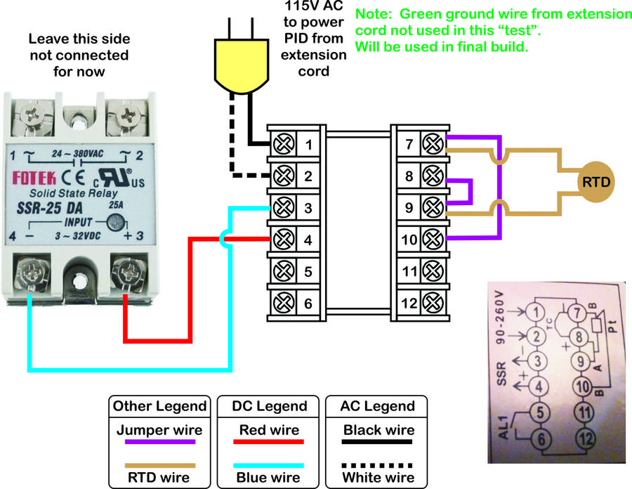
Ok, here is part 2 where we add the 115v power that will run the heater. Don't add this part until you have the first part working (red LED's on the PID and the SSR go on and off as the temp changes indicating the SSR is being switched properly by the PID according to temps).
- Make sure the extension cord is unplugged from the wall before starting this part.
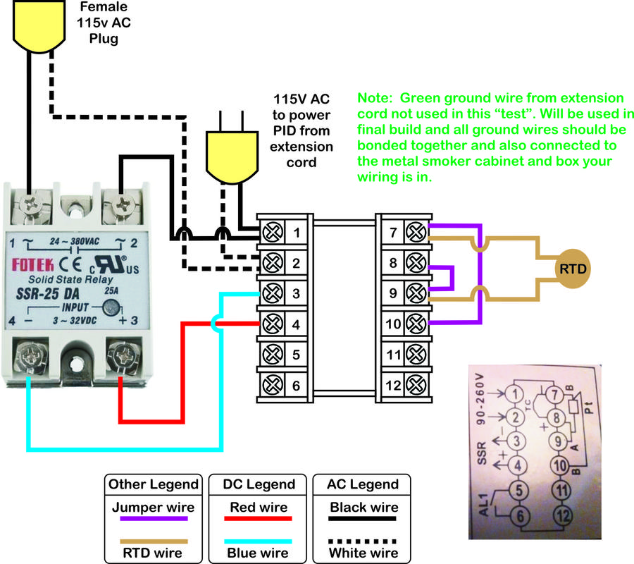
- Take the black wire from the female pigtail (cut female end of the extension cord) and attach it to terminal #1 on the SSR.
- Take the white wire from the female pigtail and attach it to terminal #2 on the PID (should be the same terminal the other white wire is on).
- Take a new black wire and attach it to terminal #2 on the SSR. Attach the other end of this new wire to terminal #1 on the PID. This black wire needs to be the same thickness (gauge) as the wires in the extension cord.
What this does is wire the pigtail in parallel with the 115v AC power coming into the PID except for a split between terminals #1 & #2 on the SSR (this is where the power is actually switched - between these two terminals on the inside of the SSR). Try and visualize a switch inside the SSR between terminals #1 and #2. There is no electrical connection between that side of the SSR and the low voltage triggering side (it's an optically isolated circuit and unlike a relay has no moving parts).
You should be able to plug a table lamp into the end of the extension cord and the light will be turned on and off depending on the PID "set point" and temperature the RTD sensor is reading.
Just make sure when you build the final version to reconnect all the ground wires and there should also be a ground wire run to the metal cabinet and box housing the electronics (you can use a wire nut to connect them on one end and the cabinet ground end should be screwed down solid). I would also add a resettable breaker or fuse to the final circuit. It would be best to add a terminal strip for power distribution before both the SSR and PID and fuse each of them separately (low amperage to protect the PID and up to the rating of your wiring for the SSR side).
Let me know if this works. It will probably be tomorrow night before I'm back online as I have a 800 question test for a new job I'm in the final running for. My brain may be fried by then anyway.....