MYPIN PID help, need switch signal to be 110V

  • Some of the links on this forum allow SMF, at no cost to you, to earn a small commission when you click through and make a purchase. Let me know if you have any questions about this.
SMF is reader-supported. When you buy through links on our site, we may earn an affiliate commission.

skys

Newbie
Original poster
Jun 9, 2014
8
10
Hi!  

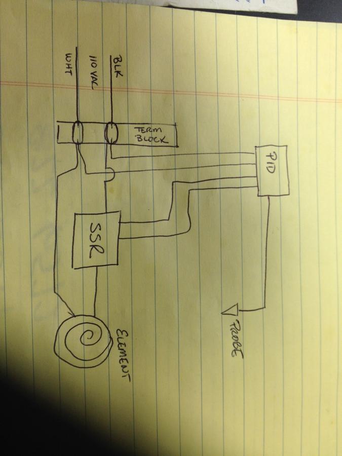
I am using a Mypin PID, and have hooked it up:

110v coming into terminals 1 & 2

Terminals 3 & 4 going to the SSR

Termianls 7 & 8 attached to the thermocouple.

I think that the problem is that my SSR needs 110v to switch on, it is a heavy duty one 240v output for my oven.  I am thinking that the signal from the PID is too weak to switch the SSR.  Can anyone help me configure my PID so that the switch signal is 110v?

Thanks!
 
What's the model number of your SSR?

I've started getting parts to build a PID system.  The SSR is a MYPID SSR-25 DA that takes an input of 3-32VDC and switches up to 360VAC.
 
MYPID TA4 SNRK.  I'll look your up and see if it would work.
 
Where did you get it?  I'm having a hard time actually finding info on that particular one...

Thanks for your help!
 
Hmmmm, I cant really tell what the difference between yours and mine is.  It looks like if I hook the SSR up to alarm 1, then I can have it output up to 250V, do you know how yours is hooked up?  Did you have to do any programming other than setting the temp?
 
I just had an electrician buddy stop by and we found that there is no Voltage coming out of the SSR output at all!  Maybe this is a defective unit?  
 
An SSR doesn't supply voltage to a device; it switches a voltage on and off.  The output contacts can be checked with an ohmmeter to verify whether they are open or closed.  The input voltage to the SSR coming from the TA4 controls whether the SSR is on or off.
 
Interesting.  So, the PID acts like the switch leg in a light socket?  Open (on) should give me a 1 on an ohm meter, closed would give me a zero?  I only know enough about electricity to make me dangerous...  I 'll run check.  

So, if I understand you correctly:  the 110v supply to my SSR should have one "leg" ( be it the white or black wire, doesn't matter) attached to the 110v supply, and the other runs through the PID?  Thanks for your help.  The electricians in my small town dont have much experience with PID controllers...
 
The way I understand it. you have power in, you splice your power in, one set of wires goes to your PID to power it. the other set of wires, One wire goes directly to your heating element, the other wire goes through your SSR like a light switch, and the SSR is switched open/closed through the control wiring coming from the PID.
 
Basically the PID is just a thermostat not unlike that for your furnace in your home.

The SSR is just an automatic switch/relay that switches 1 leg of the 110vac coming into the Element to break the circuit when it should be off,

and complete the circuit when it should be on.

The SSR is in a Normally Open state, so the element is off, when the PID has power and you tell it to reach 250 degrees, it will send low voltage power to the

SSR telling it to close the circuit, which will power the element, once the PID reaches temperature, it will de-energize the circuit that goes to the SSR allowing

it to open and turn off the element.

Hence working exactly like your home furnace.

PID - Automatic Controller

SSR - Single Leg Relay/Switch

I hope that helps.
 
 
Interesting.  So, the PID acts like the switch leg in a light socket?  Open (on) should give me a 1 on an ohm meter, closed would give me a zero?  I only know enough about electricity to make me dangerous...  I 'll run check.  

So, if I understand you correctly:  the 110v supply to my SSR should have one "leg" ( be it the white or black wire, doesn't matter) attached to the 110v supply, and the other runs through the PID?  Thanks for your help.  The electricians in my small town dont have much experience with PID controllers...
The PID is the controller.  The SSR is the switch.  On an ohmmeter, an open(off) switch(relay) will read infinity; closed(on) will read 0(zero).

Keith posted a good drawing of the way the system should be wired.  Black and white DOES matter when wiring anything.  The black (hot) wire should always be the switched line.
 
Interesting.  I think part of the problem is that the SSR that my electrician buddy got, requires 110v to switch it on.  When I attach it to 110V, it clicks open and sends power to the elements.  He probably over-spec'd it as it is a 15A 240V stove.  Can the above drawing be used with a simple SSR?  My bet is yes.  I think that if I get a different SSR, one which does NOT require 110v, but rather requires low voltage, that the system will work.  I ordered a new PID and SSR yesterday (just to be sure that my PID was not faulty).  Will post the results.

Thanks for your help!
 
The drawing can be used for any setup, it was a quick sketch on my pad here at the desk.

I would put 2 inline fuses on the black lines though, a 2a fuse going to the PID and a 20a fuse going to the SSR.

Just to save having to buy parts if there is ever a problem, fuses are cheap, you can use inline blade fuses from

Autozone.

Also, you probably want to put a lighted switch on the incoming black line, so you can shut off your smoker without having to unplug it.
 
FYI, a SSR needs power on the load side of the SSR to work.  If you have a SSR hooked up to a PID and try to use a ohm meter to check continuity on the load side with nothing but the meter across the bare terminals, the SSR will not switch.  There is a slight feedback current from the load power that is needed to change the state of the SSR (in english it needs power on the load side or it will not turn on and off).   So don't panic if you have tried using a meter to check your SSR.  It is not going to work with just a meter.

Here is a example wiring diagrams that might be helpful.  The heating element goes where the "plug" is in this set of diagrams (it was originally to help a member who used a plug on his setup).  I suspect you have what he did as illustrated in the third diagram.  There is no source of power for the load in that diagram as the PID only provides a triggering signal and not a voltage to the load.


SmokingMeatForums.com is reader supported and as an Amazon Associate, we may earn commissions from qualifying purchases.
Clicky